Benchmark
Introduction
This technical write-up presents the preliminary energy consumption measurements and estimated battery life for devices utilizing the Arach protocol developed by Oscilx Labs. These results are initial findings and should be considered as such, with significant improvements expected in future hardware and software revisions.
Hardware
The tests are conducted using the nodes described in the Proof of Concept hardware section. The nodes have an ARM Cortex M0+-based microcontroller(STM32G030F6P6TR) and a 2.4GHz radio(NRF24L01+) connected over a full duplex SPI bus. The device hardware configuration is as follows:
| Parameter | Value |
|---|---|
| Core Clock | 16MHz |
| Core Clock Source | Internal Oscillator |
| Timing Clock | 32.768kHz |
| Timing Clock Source | External Quartz Crystal |
| Low Power Mode | Stop 1 Reference Manual |
| SPI Frequency | 8MHz |
| Radio TX Power | MAX(+0dBm) |
| Radio Data Rate | 250kbps |
| Radio Frequency | Selected by dynamic channel hopping |
| Radio Auto Retransmission | Off (Handled by link layer) |
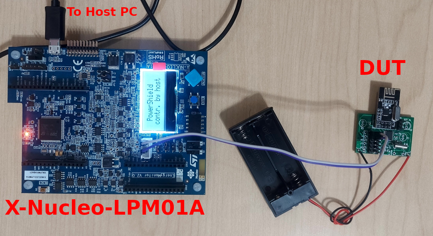
Power measurements were performed using the X-NUCLEO-LPM01A, a precision ultra-low power source-measure unit capable of measuring currents in the 100nA to 50mA range while outputting a programmable voltage between 1.8-3.3 Volts. The sampling frequency can range between 1-100kSps. This is the standard for several industry-wide low-power benchmarks like EEMBC ULPMark™.
The test equipment configuration is as follows:
| Parameter | Value |
|---|---|
| Sampling Frequency | 10kSps |
| Input Voltage (for DUT) | 2600mV |
The target voltage was set to 2600mV as alkaline cells spend most of their discharge cycle near this value, giving us a closer estimate for battery life.
The device under test(DUT) was attached to the power meter which was then connected to the host computer for data logging.

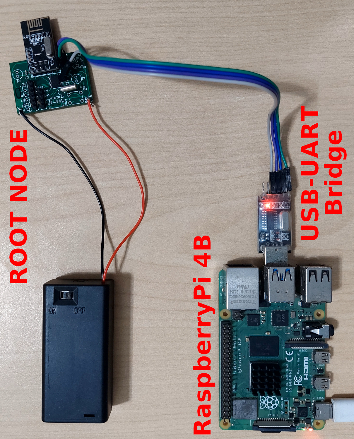
The network root node was the collection point for the logs and data generated by the network. It was not connected to the computer logging the power measurements as the DUT and root would be too close, making the packet losses artificially low. So the root was connected to a Raspberry Pi 4B using a USB-UART bridge for data logging.

Software
For a detailed explanation of the parameters discussed in this section, please refer to the Protocol Primer.
All nodes except the root run the same program based on the Arach protocol. The root has additional logging and UART commands for network control accessible by the host computer. The nodes generate a 25-byte packet every 30 seconds that contains timing, power source voltage and temperature data.
The code was compiled using the ARM-LLVM toolchain with the major parameters being:
| Parameter | Value |
|---|---|
| COMMUNICATION_INTERVAL | 30s |
| ADVERTISEMENT_INTERVAL | 300s |
| MAX_CHILDREN | 2 |
This means devices would communicate every 30 seconds, accept a maximum of 2 direct children and advertise every 300 seconds.
Power measurements were recorded using the STM32 CubeMonitor-Power application.
Baseline Measurements
During intermittent idle periods, the devices were put into a deep sleep state with a low-power timer running to wake up after a specified interval. In this state, the microcontroller shuts down its CPU, peripherals, flash memory and all clocks except the one used by the low-power timer. The contents of the RAM are retained. All microcontroller GPIO pins are pulled down to prevent current leakage from pins in a floating state. The radio is put in power-down mode. In this state, the device draws the least current which fluctuates between 4-5µA depending on the temperature. For the rest of the discussion, 4.5µA will be considered the baseline consumption.
Test Cases
In all test cases, the DUT is a child of the root node. The configurations are:
- DUT with no children
1
(ROOT NODE) ---- (DUT)
- DUT with one direct child
1
(ROOT NODE) ---- (DUT) ---- (DIRECT CHILD)
- DUT with one direct child and one indirect child
1
(ROOT NODE) ---- (DUT) ---- (DIRECT CHILD) ---- (INDIRECT CHILD)
- DUT with two direct children
1
2
3
4
5
6
7
                 (DIRECT CHILD 1)
                        /
                      /
(ROOT NODE) ---- (DUT)
                      \
                        \
                 (DIRECT CHILD 2)
- DUT with two direct children and one indirect child
1
2
3
4
5
6
7
                     (DIRECT CHILD 1)
                        /       \
                      /           \
(ROOT NODE) ---- (DUT)      (INDIRECT CHILD)
                      \
                        \
                     (DIRECT CHILD 2)
Measurements converged to a stable number within 30 minutes. Regardless, tests were run for at least 2 hours in each configuration. Some tests were allowed to run longer as they ran overnight.
Results
| Test | DN | Max Current(µA) | Avg Current(µA) | Increase(µA) | Result Images |
|---|---|---|---|---|---|
| 1 | 0 | 18005.371 | 7.794 | 3.294 | No child |
| 2 | 1 | 18035.889 | 10.803 | 6.303 | 1 direct child |
| 3 | 2 | 18173.218 | 13.352 | 8.852 | 1 direct 1 indirect children |
| 4 | 2 | 18112.183 | 14.423 | 9.923 | 2 direct children |
| 5 | 3 | 18112.183 | 16.219 | 11.719 | 2 direct 1 indirect children |
DN: Downstream Nodes(direct +indirect children)
Note: Increase calculated over the baseline of 4.5µA
Note: Max Current values for tests 4 and 5 are equal and not a copying error.
For each new downstream node added, the power consumption rises by around 2-3µA.
Battery Life Estimation
-
2xAA alkaline cells
A typical AA alkaline cell contains about 2800mAh usable capacity for the current prototype device(cutoff at 2.1 volts, 1.05 volt per cell). Other factors to consider are the battery self-discharge at 3% per annum and a rated life of 10 years. Taking these into account, a simple calculation reveals that the nodes will outlast the shelf life of the cells, giving us a 10-year battery life. -
CR2032 lithium coin cell
This is another popular power source for low-power devices and wearables. The cell has about 230mAh capacity and a low self discharge rate of 1% per annum. Taking these numbers into account we get:
| Test | Downstream Node Count | Avg Current(µA) | CR2032 Battery Life(years) |
|---|---|---|---|
| 1 | 0 | 7.794 | 3.259 |
| 2 | 1 | 10.803 | 2.372 |
| 3 | 2 | 13.352 | 1.929 |
| 4 | 2 | 14.423 | 1.788 |
| 5 | 3 | 16.219 | 1.593 |
Conclusions
The experimental results showcase the power efficiency of the Arach mesh protocol. It achieved these results while using minimal resources. The power consumption results are on the higher side as the hardware used is general purpose and not fully low-power optimized. The measured current in the stop and transmission mode is 4.5µA and 18mA respectively which matches the datasheets. With the planned shift to a newer RF SOC, these numbers are expected to drop to <1µA and 5.6mA for similar parameters while still remaining competitive in price and performance.