Proof of concept
Introduction
Here we describe a test run of Arach. To effectively test the protocol stack a prototype hardware was assembled. The network was allowed to run for about one day and node-level metrics were collected, plotted and analyzed.
Protocol Primer
Arach works by aggressively duty cycling the wireless device’s radio to conserve power, this means that the radio is switched on only when both sender and receiver are ready to communicate and is switched off promptly after that. The power consumption of the device is directly dictated by how long, how frequently and in which mode the radio stays on.
The “how long” is dictated by the amount of data that needs to be transmitted and is calculated by the protocol.
The transmission frequency is based on the user’s needs and is chosen to balance power consumption and latency. A higher frequency of communication affords lower latency at the cost of a higher power budget and vice versa. This is controlled by user-defined parameters(COMMUNICATION_INTERVAL) and can be set from as low as 20 milliseconds to as large as 194 days, though it is advised to keep it under 5 hours.
Besides data transmission, the nodes in the network also need to advertise their existence for other nodes to join. This advertisement is sent periodically based on a configurable period(ADVERTISEMENT_INTERVAL). The advertisements are stopped when a node has accepted a set number of direct children(MAX_CHILDREN) which is user-configurable based on the topology desired.
Hardware
The software stack is lightweight with very few feature requirements. The microcontroller needs to have at least:
- 20kB of program memory(flash)
- 4kB of data memory(SRAM)
- RTC with wake-up capability
- Capability to interface with the radio
- 1 UART for logging and control
- A low power mode for power consumption
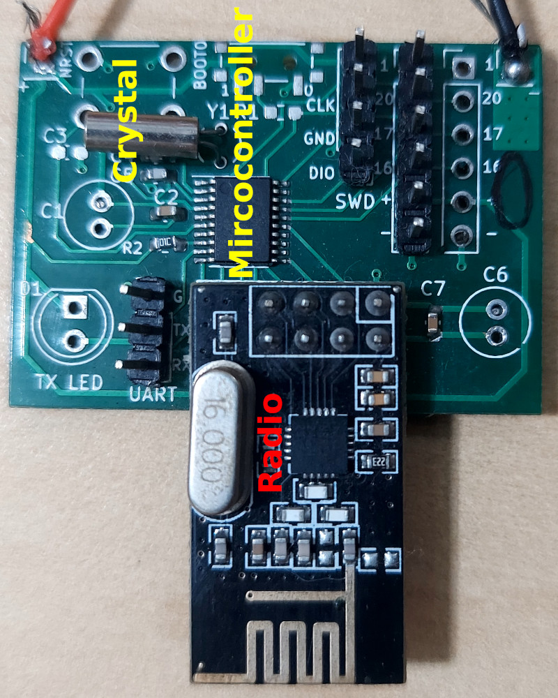
To showcase the low resource utilization, we went with the cheapest mainstream microcontroller available that satisfied the requirements, the STM32G030F6P6TR (product page). The ARM Cortex M0+ CPU, though capable of running up to 64MHz was clocked at the default 16MHz as the device functioned properly even at the slower clock (Can be reduced further, but this wasn’t the objective of the tests conducted, for now).
For the radio, Arach requires support for:
- Sending data
- Receiving data
- Carrier frequency change
- Power down modes
That’s it! Packet integrity checks typically performed by the radio baseband are done by the software using lightweight cryptographic algorithms. This method eases the requirements for the radio hardware while utilizing the CPU idle time.
The radio chosen for the prototype is NRF24L01+ operating in the 2.4GHz ISM band. It fulfills all the requirements and the advanced features like auto-retransmission and acknowledgements it supports can be easily disabled as these are handled by the software. It connects to the microcontroller using an 8MHz full-duplex SPI bus.
The final device has a microcontroller, a radio and a 32.768kHz crystal on a PCB and is powered by 2xAA alkaline cells. It is programmed using the SWD headers. Four unused GPIO pins are exposed as headers for attaching sensors and debug probes.
 An LDR with a series resistor is added between the VDD and ground and the junction of both components is connected to one of the pins of the microcontroller configured as analog input.
Software
The main parameters defining the network were set as follows:
| Parameter | Value |
|---|---|
| COMMUNICATION_INTERVAL | 10sec |
| ADVERTISEMENT_INTERVAL | 60sec |
| MAX_CHILDREN | 2 |
The devices ran an application that measured the supply voltage(VDD) and light intensity values using the LDR and the internal voltage reference of the ADC in the microcontroller. The data was packed into a packet along with a timestamp and transmitted every 10 seconds. The network was also set to periodically generate node metric packets that recorded the time each node spent in transmit and receive modes.
The Arach stack along with the application was compiled using the ARM Compiler 6(AC6). The resulting binary required 15kB flash and 3kB SRAM. The unused 5kB SRAM was allocated to make the network buffers larger than their default configuration to use all available space. The software is written to allocate all memory statically and has been tested using address sanitizers and static code analyzers to ensure memory safety.
Note: The build system now supports GCC and LLVM toolchains in addition to Keil.
The device exposes two UART interfaces:
- System UART: For issuing administrative commands and logging system-level info in debug builds
- Application UART: Used by the user as they deem fit
Note: Newer versions allow multiplexing on the same UART interface for saving resources.
The stream demultiplexer will be provided as a C and Python function
Experiment
The test involved 9 nodes, 1 root and 8 network nodes. The network nodes were flashed with the program and kept in different rooms/corridors making sure each node had a minimum of 20 meters or 1 brick wall separating it from all other nodes. The testing was done in a residential complex with many 2.4GHz WiFi access points and other interfering equipment.
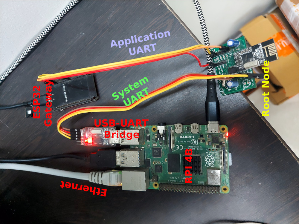
The root node was connected to an ESP32 which acted as a gateway for the network. The root sent all data received via the application UART to the ESP32 which inserted it into a PostgreSQL instance running in the cloud. The system UART was routed to a Raspberry Pi 4B for log collection and analysis, no administrative commands were issued to the root node. The RPI was also acting as a WiFi access point to which the ESP32 connected for internet access. The final setup looked like this:

Placing the root node close to such a high RF activity area was intentional and part of the endurance test to gauge the impact and effectiveness of the channel hopping scheme against harsh RF environments (there were three devices connected to the RPI access point at all times during the test).
The application on the root node received data from all the network nodes and serialized it to send to the ESP32 gateway. The data flow for this UART looked like:
1
(ROOT NODE | APP UART)--UART->(ESP32)--WiFi->(RPI)--Internet->(Cloud | PostgreSQL)
The system UART logged data directly to a file which could be analyzed in real time or later.
1
(ROOT NODE | SYS UART)--UART->(RPI | log.txt)--SSH->(Computer | Log analysis scripts)
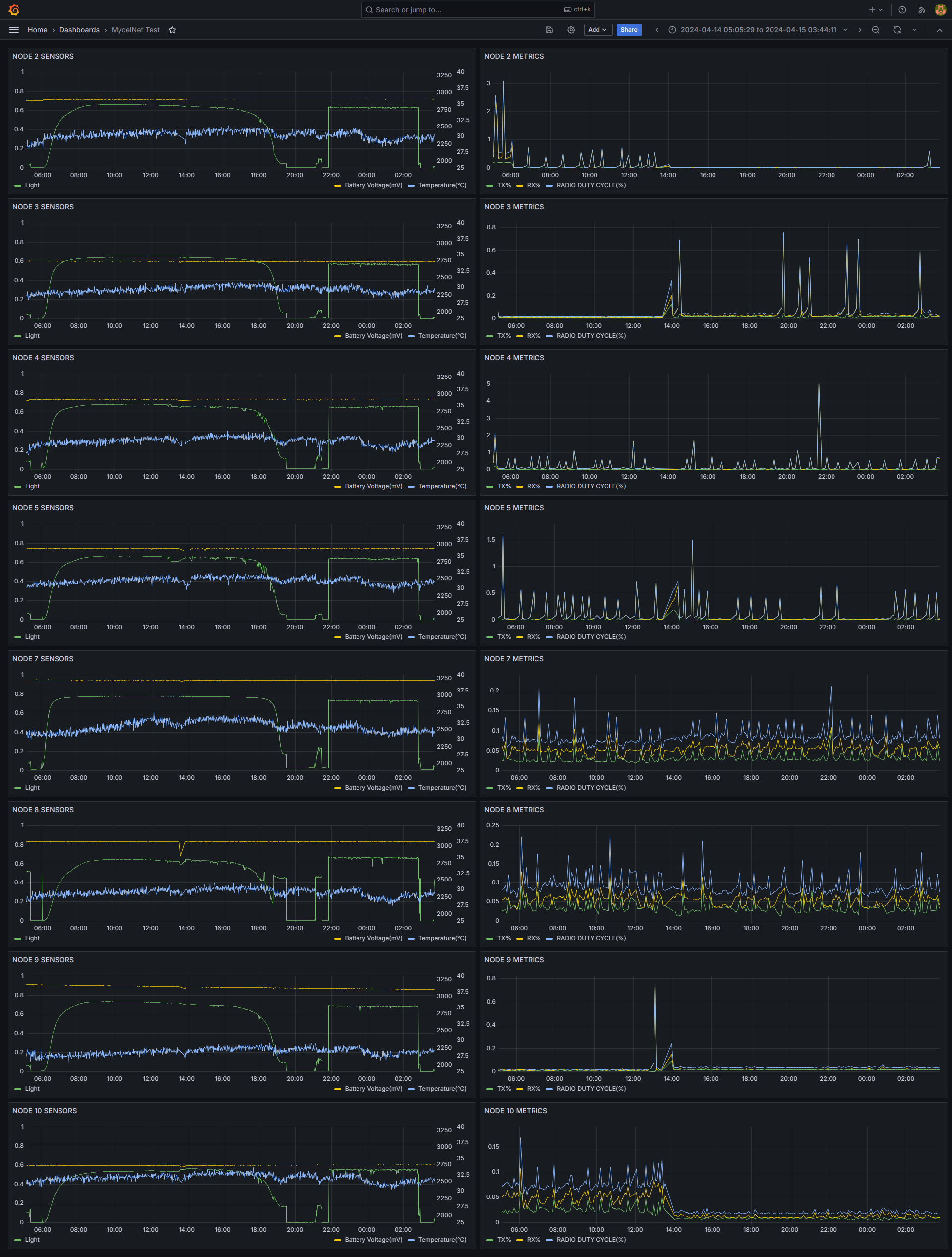
A Grafana dashboard was set up to view the recorded sensor data.
The test was run for about one day and the data recorded is as follows:

All the nodes averaged out to a radio duty cycle well below 0.3%, with the nodes closer to the root having higher average duty cycles as they routed packets not generated by them. No packets were lost during the test because of a robust retransmission mechanism.
Conclusion
The software stack was successfully tested on the custom hardware and produced results as promised. The tests also demonstrated Arach’s capability to run on one of the lowest-end microcontrollers thereby validating its low resource utilization claims. Since this proof of concept test was run, the software has gone through a few iterations, adding new features and ironing out issues like the spikes in the duty cycles seen in the dashboard plots.
Do check out the benchmark tab to see the power consumption measurements taken using industry-standard equipment for the latest version of the software.